Email:
info@sparqee.com
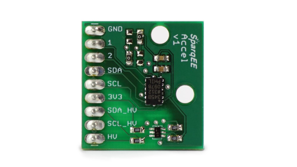
SparqEE ACCELv1.0

Special Features:
- Accelerometer Development Board
- I2C Line: 3.3-15V
- 2 Interrupt Lines
The GPSv1.0 is provided as a wide input range Accelerometer development board. Most development environments provide a 3.3V output but sometimes utilize higher voltage I/O lines (Arduino is 5V I/O, Raspberry Pi is 3.3V I/O). This board can support any voltage I/O lines up to 15V.
Power
- Supply: 2.0 to 3.6V (for 3.3V)
- I/O: 2.0 to 15V
Physical
- 24mm x 23mm (0.94″ x 0.91″)
Operating Temperature
- -40°C to +85°C
Pin Assignment:
| Pin | Function | Optional/Required | Voltage | I/O |
| GND | Ground connection | Required | 0 | I |
| 1 | Interrupt 1 from ADXL345 | Optional | 3.3V | O |
| 2 | Interrupt 2 from ADXL345 | Optional | 3.3V | O |
| SDA | I2C SDA line | Optional | 3.3V | I/O |
| SCL | I2C SCL line | Optional | 3.3V | I/O |
| 3V3 | 3.3V power line | Required | 3.3V | I |
| SDA_HV | I2C SDA line, HV | Optional | 3V3-15V | I/O |
| SCL_HV | I2C SCL line, HV | Optional | 3V3-15V | I/O |
| HV | High Voltage power line (required if using HV I2C line) | Optional | 3V3-15V | I |
Code:
Arduino
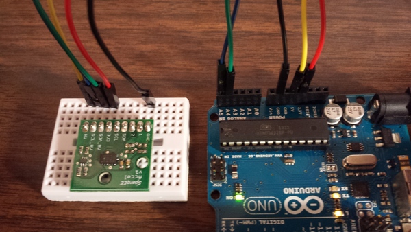
Connect the following pins:
| Pin | # | Function | Procedure | Voltage | I/O | Arduino |
| GND | 1 | Ground connection | Static connect | 0 | I | GND |
| 3V3 | 6 | 3.3V power line | Static connect | 3.3V | I | 3.3V |
| SDA_HV | 7 | I2C SDA line, HV | I2C communication | 5V (3.3-15V) | I/O | A4 |
| SCL_HV | 8 | I2C SCL line, HV | I2C communication | 5V (3.3-15V) | I/O | A5 |
| HV | 9 | High Voltage power line (required if using HV I2C line) | Static connect | 5V (3.3-15V) | I | 5V |

Accelerometer Output – Passing Condition:
0|-1|118
2|95|85
-40|40|102
-63|2|91
4|-79|86
82|28|88
3|69|113
-83|44|101
-3|20|-138
4|18|-132
24|33|73
1|6|117
1|6|117
1|7|119
1|7|117
1|1|117
Accelerometer Output – Failing Condition:
A failing condition looks like the following. The numbers will stay continuous no matter the movement or rotation direction.
26881|26625|26369
26881|26625|26369
26881|26625|26369
26881|26625|26369
26881|26625|26369
26881|26625|26369
26881|26625|26369
26881|26625|26369
26881|26625|26369
26881|26625|26369
26881|26625|26369
26881|26625|26369
