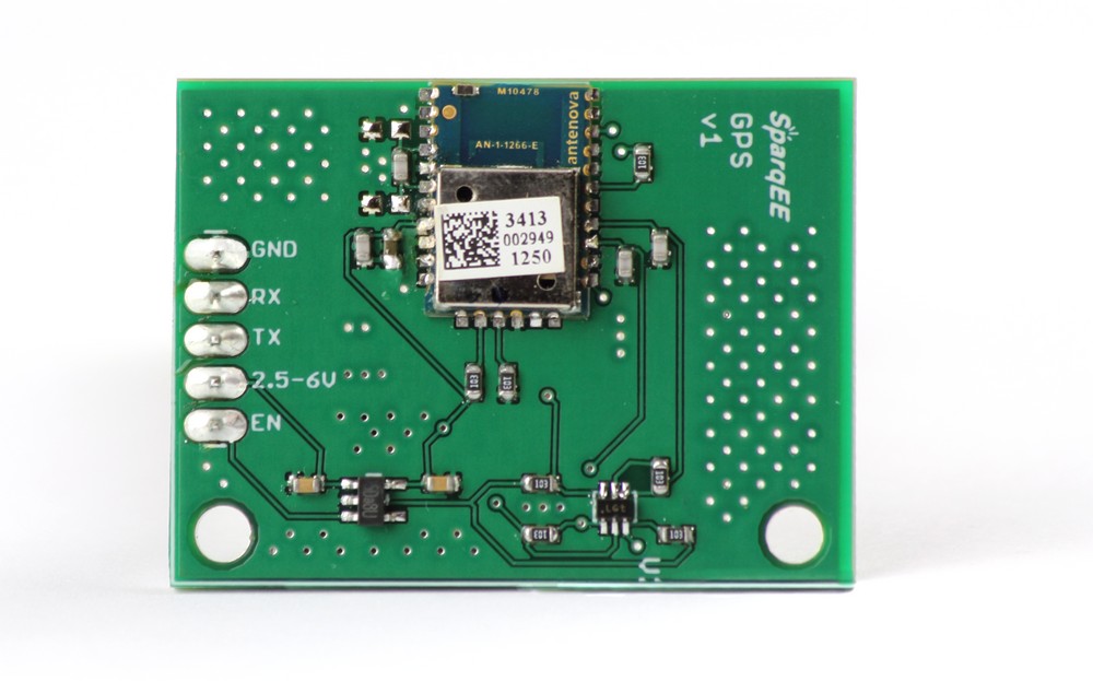
SparqEE GPSv1.0

Special Features:
- GPS Development Board
- Power/IO: 2.5-6V
The GPSv1.0 is provided as a wide input range GPS development board. Most development environments provide a 3.3V output but sometimes utilize higher voltage I/O lines (Arduino is 5V I/O, Raspberry Pi is 3.3V I/O). This board can support any voltage I/O lines up to 6V.
Power
- Supply voltage range: 2.5-6V
Physical
- 23mm x 40mm (0.91″ x 1.57″)
Operating Temperature
- -40°C to +85°C
Pin Assignment:
| Pin | Function | Optional/Required | Voltage | I/O |
| GND | Ground connection | Required | 0 | I |
| RX | Receive | Required | 2.5-6V | I |
| TX | Transmit | Required | 2.5-6V | O |
| 2.5-6V | Power input | Required | 2.5-6V | I |
| EN | Enable power module | Required | 2.5-6V | I |
Code:
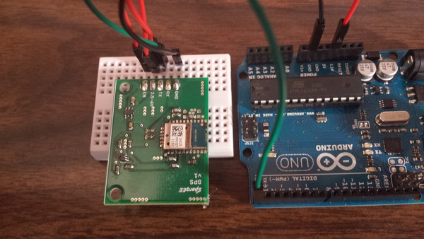
Connect the following pins:
| Pin | # | Function | Procedure | Voltage | I/O | Arduino |
| GND | 1 | Ground connection | Static connect | 0 | I | GND |
| TX | 3 | Transmit | UART communication | 5V (2.5-6V) | I | RX |
| 2.5-6V | 4 | Power input | Static connect | 5V (2.5-6V) | I | 3.3V |
| EN | 5 | Enable power module | Static connect | 5V (2.5-6V) | I | 3.3V |

Note: Since the GPS board uses TX/RX on the Arduino board, it must be unplugged from the Arduino board when programming.
The following is GPS output before it attains a lock. You’ll see mostly commas, especially noting the GPGGA line which does not contain required coordinates:
$GPGGA,080325.199,,,,,0,00,,,M,0.0,M,,0000*5B
$GPGSA,A,1,,,,,,,,,,,,,,,*1E
$GPRMC,080325.199,V,,,,,,,240314,,,N*40
$GPGGA,080326.199,,,,,0,00,,,M,0.0,M,,0000*58
$GPGSA,A,1,,,,,,,,,,,,,,,*1E
$GPRMC,080326.199,V,,,,,,,240314,,,N*43
$GPGGA,080327.199,,,,,0,00,,,M,0.0,M,,0000*59
$GPGSA,A,1,,,,,,,,,,,,,,,*1E
$GPRMC,080327.199,V,,,,,,,240314,,,N*42
$GPGGA,080328.199,,,,,0,00,,,M,0.0,M,,0000*56
$GPGSA,A,1,,,,,,,,,,,,,,,*1E
$GPRMC,080328.199,V,,,,,,,240314,,,N*4D
$GPGGA,080329.199,,,,,0,00,,,M,0.0,M,,0000*57
$GPGSA,A,1,,,,,,,,,,,,,,,*1E
$GPGSV,3,1,12,02,14,214,29,04,64,182,24,05,00,000,21,10,00,000,23*7E
$GPGSV,3,2,12,12,03,334,26,08,57,094,,23,52,187,,27,52,110,*76
$GPGSV,3,3,12,03,36,332,,09,32,128,,24,27,212,,17,26,350,*7B
GPS output once lock is attained. GPGGA coordinates filled in versus the commas seen above, for example $GPGGA,031350.000,3355.3471,N,11751.7128,W. The third and fourth fields denote valid Latitude and the fifth and sixth fields denote a valid Longitude.
$GPGSA,A,3,17,09,28,08,26,07,15,,,,,,2.4,1.4,1.9*.6,1.7,2.0*3C
$GPRMC,031349.000,A,3355.3471,N,11751.7128,W,0.00,143.39,210314,,,A*76
$GPGGA,031350.000,3355.3471,N,11751.7128,W,1,06,1.7,112.2,M,-33.7,M,,0000*6F
$GPGSA,A,3,17,09,28,08,07,15,,,,,,,2.6,1.7,2.0*3C
$GPGSV,3,1,12,17,67,201,30,09,62,112,28,28,57,022,21,08,55,104,20*7E
$GPGSV,3,2,12,07,25,124,22,15,24,302,30,11,17,052,26,26,49,262,05*73
$GPGSV,3,3,12,30,51,112,31,57,31,122,,01,24,073,,04,05,176,*7E
$GPRMC,031350.000,A,3355.3471,N,11741.7128,W,0.00,143.39,210314,,,A*7E
$GPGGA,031351.000,3355.3471,N,11741.7128,W,1,07,1.4,112.2,M,-33.7,M,,0000*6C
You can use the standard Raspberry Pi UART and functions to capture GPS data over the HW UART or, as demonstrated below, you can use the Raspberry Pi to “Bit Bang” or port “Software Serial” rather than the Hardware one.
The below software Serial port utilizes the great PIGPIO which you can download and install for free at the following URL:
http://abyz.co.uk/rpi/pigpio/download.html
Here’s the file I used from their site and the installation on the Raspberry Pi:
wget abyz.co.uk/rpi/pigpio/pigpio.zip
unzip pigpio.zip
cd PIGPIO
make
sudo make install
#!/usr/bin/python

import sys
import time
import difflib
import pigpio

RX=18

try:
        pi = pigpio.pi()
        pi.set_mode(RX, pigpio.INPUT)
        pi.bb_serial_read_open(RX, 9600, 8)

        print "DATA - SOFTWARE SERIAL:"
        while 1:
                (count, data) = pi.bb_serial_read(RX)
                if count:
                        print data
                time.sleep(1)

except:
        pi.bb_serial_read_close(RX)
        pi.stop()
